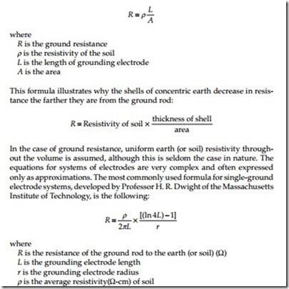
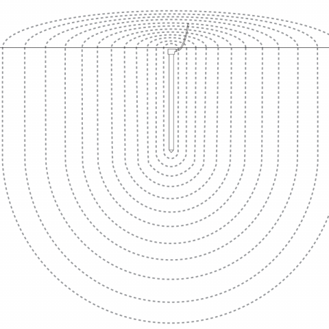
Ground Rod Resistance Formula
Electrical Power System Grounding And Ground Resistance Measurements Understanding Ground Resistance Electrical Power Generation

How To Calculate The Apparent Resistivity In The Cases Of Horizontal And Vertical Electrodes

Measurements And Calculations Of Earth Electrode Systems Bs 7430 Eep
Calculating Ground Electrode Resistance Of A Single Rod Ground Electrode Design Principles And Testing Nvent

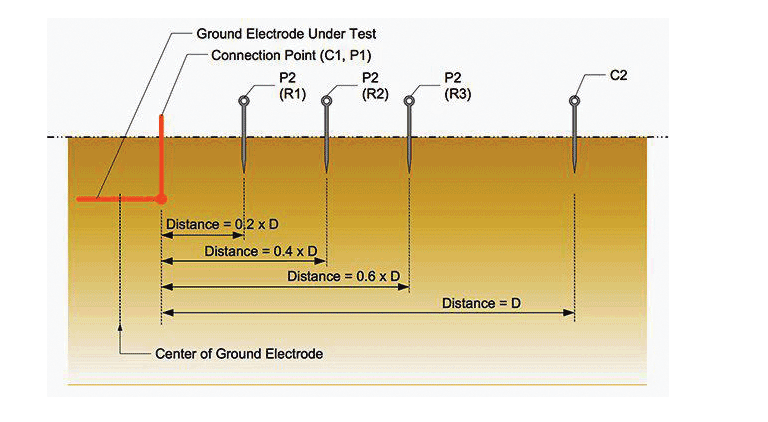
Basics Of Ground Rod Testing Ppt Video Online Download

Understanding Soil Resistivity Testing Shopaemc Com

Earthing resistance and number of rods for isolated earth pit without buried earthing strip the earth resistance of single rod or pipe electrode is calculated as per bs 7430.
Ground rod resistance formula.
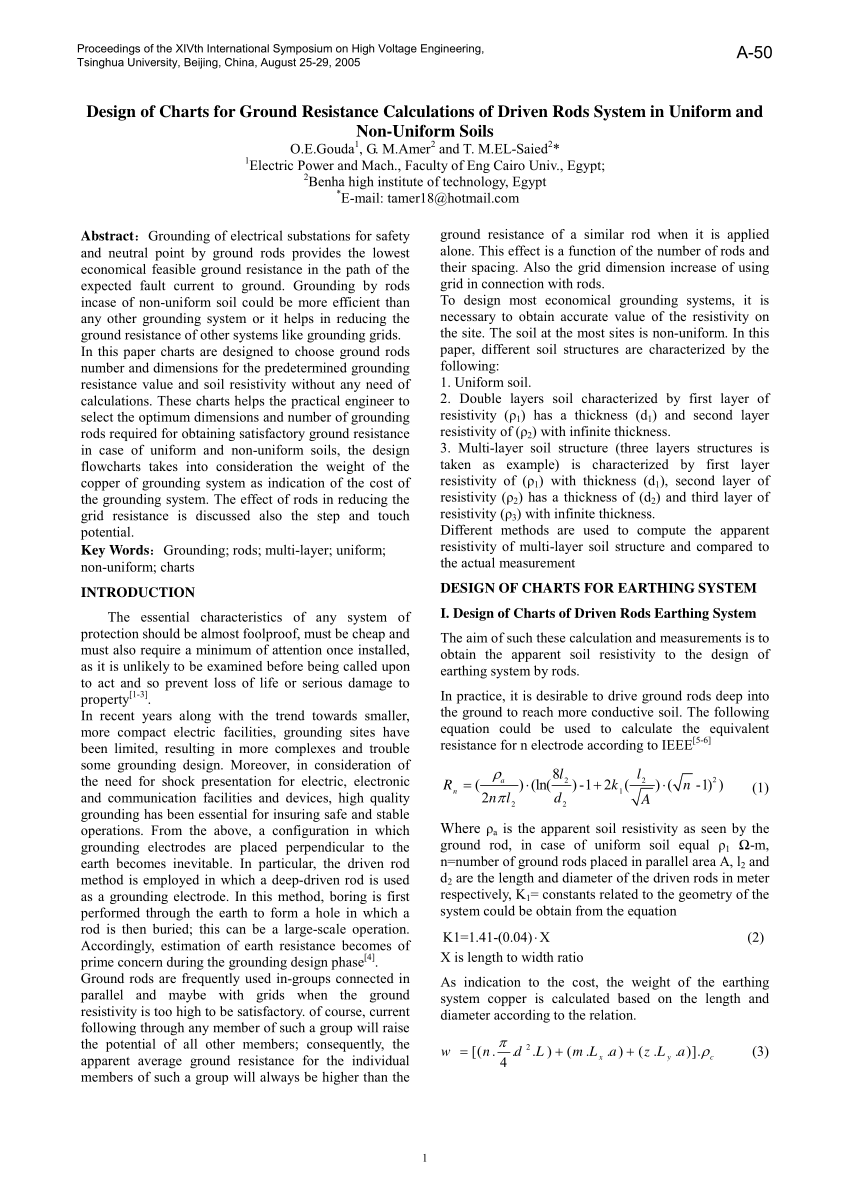
Pdf Design Of Charts For Ground Resistance Calculations Of Driven Rods System In Uniform And Non Uniform Soils

Earth Electrode Testing Youtube

Understanding Soil Resistivity Testing Utility Products
Earthing Resistance And Measurement Practices Electrical Power Review Case Study
Source : pinterest.com
